- Products
- Air Compressors & Air Tools
- Climate Control
- Compaction Equipment
- Concrete Cutting Tools & Equipment
- Concrete and Masonry
- Demolition & Excavation
- Electrical & Mechanical
- Fasteners and Anchoring Adhesives
- Floor Protection
- Generators and Welders
- Hand Tools
- Heaters
- Janitorial and Office Supplies
- Jobsite Protection
- Ladders & Storage
- Lighting & Lighting Accessories
- Man Lifts
- Material Handling Equipment
- Power Tools
- Pressure Washers & Pumps
- Safety Gear
- Safety Products
- Saws
- Surface Preparation
- SEASONAL PRODUCTS
- Rentals
- Air Compressor and Air Tool Rentals
- Climate Control Rental
- Compaction Rentals
- Concrete Equipment Rentals
- Demolition & Excavation Equipment Rentals
- Concrete Floor Grinder Rentals
- General Construction Equipment Rentals
- Generator Rentals and Welder Rentals
- Heater Rentals
- Light Tower Rentals
- Man Lift Rentals in Massachusetts and Rhode Island
- Material Handling Equipment Rentals
- Pressure Washer & Pump Rentals
- Saw Rentals in New England
- SEASONAL PRODUCTS
- Products
- Air Compressors & Air Tools
- Climate Control
- Compaction Equipment
- Concrete Cutting Tools & Equipment
- Demolition & Excavation
- Electrical & Mechanical
- Floor Protection
- Generators and Welders
- Construction Heaters
- Construction Ladders, Staging, & Storage
- Construction Lighting
- Man Lifts
- Material Handling Equipment
- Industrial Janitorial and Office Supplies
- Pressure Washers & Pumps
- Construction Safety Products
- Construction Safety Gear
- Surface Preparation
- Building Protection
- Diesel Accessories
- Zero Emissions
- Rentals
- Air Compressor and Air Tool Rentals
- Climate Control Rental
- Compaction Rentals
- Concrete Equipment Rental
- Demolition & Excavation Equipment Rental
- General Construction Equipment Rental
- Generator Rentals and Welder Rentals
- Construction Heaters Rental
- Light Tower Rentals
- Man Lift Rentals
- Material Handling Equipment Rental
- Pressure Washer & Pump Rentals
- Saw Rentals in New England
- Concrete Floor Grinder Rentals
- Zero Emissions Rentals
- Repairs & Used
- Parts
- Blog
- Services
- Resources
- About Us
- Contact Us
Sales & Rental of Construction | Industrial Equipment & Supplies


2026 Best Pump Shaft Seal Types for Global Buyers?
Selecting the right Pump Shaft Seal is a reliability decision, not a simple component purchase. Global buyers face changing fluids, pressures, temperatures, regulations, and maintenance capabilities. A seal that performs well on clean water may fail quickly with abrasive slurry or crystallizing chemicals.
The U.S. Department of Energy’s pumping-system guidance links poor pump performance with significant industrial energy waste. Its assessment methods emphasize leakage control, correct sizing, alignment, and system efficiency. Small details matter. A worn sleeve can mark the shaft. A dry-running face can overheat within minutes. These failures increase downtime, product loss, and maintenance costs.
API Standard 682 provides widely recognized practices for mechanical seals used in petroleum, natural gas, and chemical services. ISO 21049 also defines important seal design and testing considerations. These standards support better purchasing decisions, but they do not replace application engineering. The European Commission’s industrial energy-efficiency materials similarly stress lifecycle performance rather than purchase price alone.
There is no universal winner.
This 2026 guide compares single mechanical seals, double seals, cartridge designs, split seals, bellows seals, and packing solutions. It considers pressure, speed, temperature, shaft movement, fluid compatibility, emissions control, installation time, and spare-part access. It also examines regional supply risks and service expectations for international buyers.
Some recommendations remain conditional. Manufacturer data may not reflect every operating cycle. Field experience can expose weaknesses that brochures overlook. Therefore, buyers should verify materials, elastomer compatibility, face combinations, flush plans, and failure records before approval. The best Pump Shaft Seal is the one matched to the real pump duty, not merely the lowest quoted price.
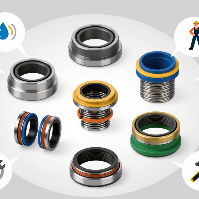
Table of Contents [Hide]
What Is a Pump Shaft Seal and Why Does It Matter?
2026 Best Pump Shaft Seal Types for Global Buyers?
What Is a Pump Shaft Seal and Why Does It Matter?
A pump shaft seal closes the gap around a rotating shaft. It prevents liquid from escaping the pump housing. It also keeps dust, air, and moisture away from internal parts. Without this barrier, bearings may corrode, floors may become slippery, and operating costs can rise. The seal works under pressure, heat, vibration, and chemical exposure.
Mechanical seals suit many modern process pumps. Their rotating and stationary faces create a controlled sealing surface. Packed glands remain useful for abrasive liquids and simpler equipment. Cartridge seals can reduce installation errors because key parts arrive preassembled. For global buyers, the best choice depends on shaft speed, pressure, temperature, fluid properties, and maintenance skills. One type cannot serve every plant.
I have seen premature failures caused by poor alignment, not weak seal materials. That is the risk. A buyer should request test data, material certificates, installation limits, and replacement guidance. Check elastomer compatibility with the pumped liquid. Confirm face materials for abrasive or crystallizing fluids. Ask how the seal performs during dry running, if that condition is possible. A reliable specification should include shaft diameter, chamber dimensions, pressure range, and expected service life. Real conditions often differ from laboratory figures, so field experience deserves equal attention.

© Copyright - Pro Tool & Supply - Site by SVM E-Marketing Solutions - Sitemap
- Privacy policy