- Products
- Air Compressors & Air Tools
- Climate Control
- Compaction Equipment
- Concrete Cutting Tools & Equipment
- Concrete and Masonry
- Demolition & Excavation
- Electrical & Mechanical
- Fasteners and Anchoring Adhesives
- Floor Protection
- Generators and Welders
- Hand Tools
- Heaters
- Janitorial and Office Supplies
- Jobsite Protection
- Ladders & Storage
- Lighting & Lighting Accessories
- Man Lifts
- Material Handling Equipment
- Power Tools
- Pressure Washers & Pumps
- Safety Gear
- Safety Products
- Saws
- Surface Preparation
- SEASONAL PRODUCTS
- Rentals
- Air Compressor and Air Tool Rentals
- Climate Control Rental
- Compaction Rentals
- Concrete Equipment Rentals
- Demolition & Excavation Equipment Rentals
- Concrete Floor Grinder Rentals
- General Construction Equipment Rentals
- Generator Rentals and Welder Rentals
- Heater Rentals
- Light Tower Rentals
- Man Lift Rentals in Massachusetts and Rhode Island
- Material Handling Equipment Rentals
- Pressure Washer & Pump Rentals
- Saw Rentals in New England
- SEASONAL PRODUCTS
- Products
- Air Compressors & Air Tools
- Climate Control
- Compaction Equipment
- Concrete Cutting Tools & Equipment
- Demolition & Excavation
- Electrical & Mechanical
- Floor Protection
- Generators and Welders
- Construction Heaters
- Construction Ladders, Staging, & Storage
- Construction Lighting
- Man Lifts
- Material Handling Equipment
- Industrial Janitorial and Office Supplies
- Pressure Washers & Pumps
- Construction Safety Products
- Construction Safety Gear
- Surface Preparation
- Building Protection
- Diesel Accessories
- Zero Emissions
- Rentals
- Air Compressor and Air Tool Rentals
- Climate Control Rental
- Compaction Rentals
- Concrete Equipment Rental
- Demolition & Excavation Equipment Rental
- General Construction Equipment Rental
- Generator Rentals and Welder Rentals
- Construction Heaters Rental
- Light Tower Rentals
- Man Lift Rentals
- Material Handling Equipment Rental
- Pressure Washer & Pump Rentals
- Saw Rentals in New England
- Concrete Floor Grinder Rentals
- Zero Emissions Rentals
- Repairs & Used
- Parts
- Blog
- Services
- Resources
- About Us
- Contact Us
Sales & Rental of Construction | Industrial Equipment & Supplies


2026 Best Carbon Steel Shaft Manufacturers Worldwide?
The 2026 Best Carbon Steel Shaft Manufacturers Worldwide guide examines suppliers through practical engineering and procurement criteria. Choosing a manufacturer requires more than comparing prices or polished websites. Real performance depends on steel grade, machining accuracy, heat treatment, and delivery consistency.
Small deviations matter.
A shaft with excessive runout can create vibration, noise, and premature bearing wear. This review considers manufacturers producing shafts from common grades such as 1045, 4140, and comparable EN materials. It also examines turning capacity, grinding quality, induction hardening, surface finishing, and dimensional control. Evidence remains central. We look for material certificates, inspection reports, traceability systems, and clear tolerance data. Factory experience also matters, especially for automotive, agricultural, construction, and industrial equipment applications. Reliable manufacturers should explain how they control diameter, straightness, hardness, and surface roughness from raw material to final packing.
The ranking is not absolute.
A supplier may excel at custom prototypes but struggle with high-volume production. Another may offer excellent equipment while communicating poorly during revisions. These weaknesses deserve attention. Therefore, this guide balances technical capability, verified experience, quality management, customization support, export reliability, and customer feedback. Where public information is limited, conclusions remain cautious rather than overstated. Buyers should still request samples, audit relevant records, and confirm specifications before signing contracts. A strong Carbon Steel Shaft manufacturer is not simply the largest company. It is the partner that consistently delivers documented quality, suitable engineering support, and dependable results under real operating conditions.
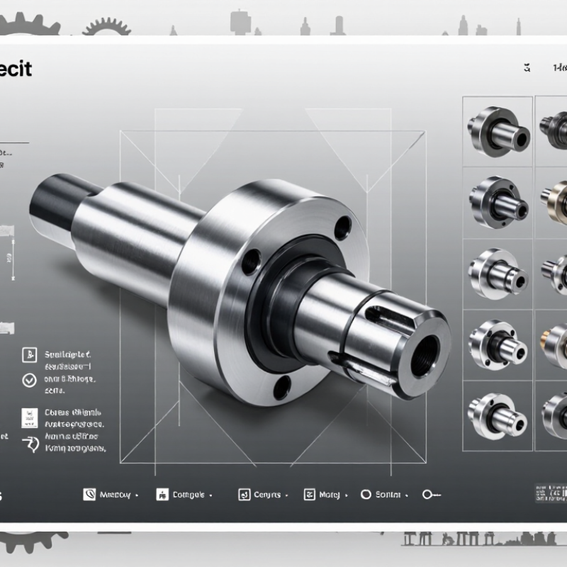
Table of Contents [Hide]
What Are Carbon Steel Shafts and Where Are They Used?
Carbon steel shafts are cylindrical machine components made from an iron-carbon alloy. They transfer torque, support rotating parts, and maintain alignment under load. Their strength comes from controlled carbon content and heat treatment. The alloy is not glamorous. It is practical, repairable, and widely available.
These shafts appear in gearboxes, electric motors, pumps, conveyors, agricultural equipment, and vehicle systems. A pump shaft may rotate through water for thousands of hours, while a conveyor shaft may carry uneven loads and repeated starts. Engineers choose diameter, steel grade, hardness, and surface finish according to torque, speed, corrosion exposure, and bending stress. Keyways, splines, threads, and shoulders must be machined accurately. Small errors matter.
Reliable manufacturers use traceable raw material, calibrated measuring tools, and documented heat-treatment controls. Buyers should request inspection data for straightness, dimensions, hardness, and surface defects. Magnetic particle testing can reveal certain cracks near the surface. Yet no production process is perfect. I have seen drawings omit fillet details, creating avoidable stress concentrations. Design reviews should question those gaps before machining begins. A low price may also hide weak traceability or inconsistent finishing. Experienced suppliers explain tolerances clearly and match testing depth to the shaft’s actual service risk.

© Copyright - Pro Tool & Supply - Site by SVM E-Marketing Solutions - Sitemap
- Privacy policy