- Products
- Air Compressors & Air Tools
- Climate Control
- Compaction Equipment
- Concrete Cutting Tools & Equipment
- Concrete and Masonry
- Demolition & Excavation
- Electrical & Mechanical
- Fasteners and Anchoring Adhesives
- Floor Protection
- Generators and Welders
- Hand Tools
- Heaters
- Janitorial and Office Supplies
- Jobsite Protection
- Ladders & Storage
- Lighting & Lighting Accessories
- Man Lifts
- Material Handling Equipment
- Power Tools
- Pressure Washers & Pumps
- Safety Gear
- Safety Products
- Saws
- Surface Preparation
- SEASONAL PRODUCTS
- Rentals
- Air Compressor and Air Tool Rentals
- Climate Control Rental
- Compaction Rentals
- Concrete Equipment Rentals
- Demolition & Excavation Equipment Rentals
- Concrete Floor Grinder Rentals
- General Construction Equipment Rentals
- Generator Rentals and Welder Rentals
- Heater Rentals
- Light Tower Rentals
- Man Lift Rentals in Massachusetts and Rhode Island
- Material Handling Equipment Rentals
- Pressure Washer & Pump Rentals
- Saw Rentals in New England
- SEASONAL PRODUCTS
- Products
- Air Compressors & Air Tools
- Climate Control
- Compaction Equipment
- Concrete Cutting Tools & Equipment
- Demolition & Excavation
- Electrical & Mechanical
- Floor Protection
- Generators and Welders
- Construction Heaters
- Construction Ladders, Staging, & Storage
- Construction Lighting
- Man Lifts
- Material Handling Equipment
- Industrial Janitorial and Office Supplies
- Pressure Washers & Pumps
- Construction Safety Products
- Construction Safety Gear
- Surface Preparation
- Building Protection
- Diesel Accessories
- Zero Emissions
- Rentals
- Air Compressor and Air Tool Rentals
- Climate Control Rental
- Compaction Rentals
- Concrete Equipment Rental
- Demolition & Excavation Equipment Rental
- General Construction Equipment Rental
- Generator Rentals and Welder Rentals
- Construction Heaters Rental
- Light Tower Rentals
- Man Lift Rentals
- Material Handling Equipment Rental
- Pressure Washer & Pump Rentals
- Saw Rentals in New England
- Concrete Floor Grinder Rentals
- Zero Emissions Rentals
- Repairs & Used
- Parts
- Blog
- Services
- Resources
- About Us
- Contact Us
Sales & Rental of Construction | Industrial Equipment & Supplies


How to Choose the Right Wired Push Button?
Choosing the right Wired Push Button is a small decision with serious operational consequences. A failed switch can stop a conveyor, delay maintenance, or create confusion during an emergency. The International Federation of Robotics reported 541,302 industrial robots were installed worldwide in 2023. That growth reflects increasingly automated workplaces, where dependable human-machine controls still matter.
The selection process should begin with the application, not the product photograph. Check the required voltage, current, contact arrangement, actuator style, and mechanical life. Confirm whether the button needs momentary or maintained action. Then examine the enclosure rating, operating temperature, vibration exposure, and cable-entry method. IEC 60947-5-1 provides important requirements for low-voltage control-circuit devices. NEMA enclosure guidance also helps engineers match protection levels to dust, water, and industrial conditions. A shiny metal button may look robust. It may not survive cutting fluid or repeated impact.
Field experience suggests that wiring details often receive too little attention. Terminal access, cable length, labeling, and replacement time can affect total ownership cost. Independent market research from Grand View Research identifies industrial automation as a rapidly expanding market, increasing pressure on manufacturers to build reliable, maintainable control panels. However, market growth does not guarantee product quality. Datasheets can omit practical weaknesses. The best choice combines verified ratings, supplier traceability, tested compatibility, and clear installation instructions. Leave room for doubt. Test the button under realistic load conditions before approving a full installation. This guide explains how to compare these factors and select a Wired Push Button that fits both the machine and the people operating it.
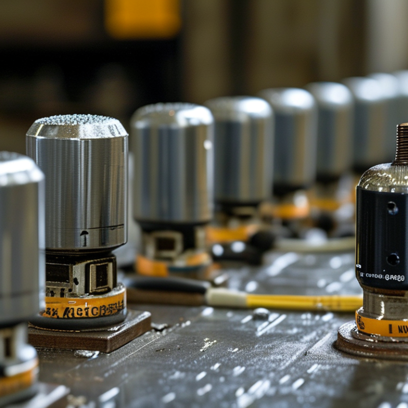
Table of Contents [Hide]
Understanding Wired Push Button Types and Operating Mechanisms
How to Choose the Right Wired Push Button?
A wired push button converts physical pressure into an electrical command. Its operating mechanism matters more than its appearance.
Momentary buttons return after release. Maintained buttons stay in position. Emergency-stop devices usually use a latching action and require deliberate resetting. Choose the mechanism based on the control sequence, not habit.
Contact blocks also shape performance. Normally open contacts close when pressed. Normally closed contacts open during activation and can support fault detection. A mechanical contact suits many low-speed circuits. A gold-plated contact may perform better with low-current signals. IEC 60947-5-1 defines key requirements for low-voltage control devices. It remains a useful reference during selection. Grand View Research valued the industrial automation market at USD 191.89 billion in 2021. Its report projected a 10.5% compound annual growth rate through 2030. More automation means more small control decisions at the machine interface. A button is simple, but its failure can stop a process.
Tips: Match voltage, current, enclosure rating, and contact configuration. Check the wiring diagram twice. Test gloves, moisture, dust, and repeated impacts. I often find that a “perfect” button feels wrong after installation. Travel may be too long. The actuator may be too small. Leave room for real operators, not only catalog measurements. Check IEC 60204-1 and applicable local requirements before commissioning.

© Copyright - Pro Tool & Supply - Site by SVM E-Marketing Solutions - Sitemap
- Privacy policy