- Products
- Air Compressors & Air Tools
- Climate Control
- Compaction Equipment
- Concrete Cutting Tools & Equipment
- Concrete and Masonry
- Demolition & Excavation
- Electrical & Mechanical
- Fasteners and Anchoring Adhesives
- Floor Protection
- Generators and Welders
- Hand Tools
- Heaters
- Janitorial and Office Supplies
- Jobsite Protection
- Ladders & Storage
- Lighting & Lighting Accessories
- Man Lifts
- Material Handling Equipment
- Power Tools
- Pressure Washers & Pumps
- Safety Gear
- Safety Products
- Saws
- Surface Preparation
- SEASONAL PRODUCTS
- Rentals
- Air Compressor and Air Tool Rentals
- Climate Control Rental
- Compaction Rentals
- Concrete Equipment Rentals
- Demolition & Excavation Equipment Rentals
- Concrete Floor Grinder Rentals
- General Construction Equipment Rentals
- Generator Rentals and Welder Rentals
- Heater Rentals
- Light Tower Rentals
- Man Lift Rentals in Massachusetts and Rhode Island
- Material Handling Equipment Rentals
- Pressure Washer & Pump Rentals
- Saw Rentals in New England
- SEASONAL PRODUCTS
- Products
- Air Compressors & Air Tools
- Climate Control
- Compaction Equipment
- Concrete Cutting Tools & Equipment
- Demolition & Excavation
- Electrical & Mechanical
- Floor Protection
- Generators and Welders
- Construction Heaters
- Construction Ladders, Staging, & Storage
- Construction Lighting
- Man Lifts
- Material Handling Equipment
- Industrial Janitorial and Office Supplies
- Pressure Washers & Pumps
- Construction Safety Products
- Construction Safety Gear
- Surface Preparation
- Building Protection
- Diesel Accessories
- Zero Emissions
- Rentals
- Air Compressor and Air Tool Rentals
- Climate Control Rental
- Compaction Rentals
- Concrete Equipment Rental
- Demolition & Excavation Equipment Rental
- General Construction Equipment Rental
- Generator Rentals and Welder Rentals
- Construction Heaters Rental
- Light Tower Rentals
- Man Lift Rentals
- Material Handling Equipment Rental
- Pressure Washer & Pump Rentals
- Saw Rentals in New England
- Concrete Floor Grinder Rentals
- Zero Emissions Rentals
- Repairs & Used
- Parts
- Blog
- Services
- Resources
- About Us
- Contact Us
Sales & Rental of Construction | Industrial Equipment & Supplies


10 Circuit Breaker Box Buying Tips for Global Buyers?
Global buyers need more than a low quotation when selecting a Circuit Breakers Box. The enclosure protects people, equipment, and business continuity in homes, factories, and commercial buildings. Yet product pages often hide important details.
A strong buying decision begins with clear application data. Consider voltage, current, fault level, circuit count, installation method, and ambient temperature. A dusty workshop may need stronger ingress protection than a clean office. Coastal sites can also challenge metal enclosures through salt exposure. Small details matter. Busbar spacing, terminal capacity, labeling space, and door clearance affect installation quality. Buyers should request drawings, test reports, material specifications, and traceable manufacturer information. Certification must match the destination market and the intended installation. IEC, UL, or other marks should never be accepted without checking their scope. Local electrical professionals should confirm compatibility with national requirements. This step can prevent expensive rework.
Price still matters, but total cost matters more. Compare breaker quality, enclosure durability, logistics, warranty terms, spare parts, and technical support. A cheap box may become costly after damaged terminals or missing documentation appear. Global shipping adds risks, including moisture, impact, customs delays, and unclear responsibilities. Ask how units are packed. Ask who handles defects. Do not assume every supplier provides the same after-sales service. A practical checklist helps, although it cannot replace engineering judgment. These ten buying tips examine selection, verification, safety, delivery, and long-term reliability. They also acknowledge an uncomfortable truth: even careful buyers can overlook one critical detail. Review the decision twice. Then ask a qualified installer to challenge it.
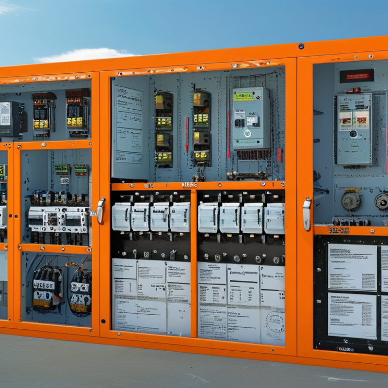
Table of Contents [Hide]
Define Your Electrical Load and Circuit Breaker Requirements
Before buying a circuit breaker box, define the electrical load in real operating conditions. List every circuit, including lighting, sockets, motors, heaters, pumps, and future equipment. Record each device’s voltage, wattage, phase, and expected running time. A small workshop may look simple, but a motor can draw several times its normal current during startup.
Create a load schedule rather than guessing from the main breaker size. Add continuous loads carefully, then apply the demand factors required by the applicable local electrical standard. Check whether the supply is single-phase or three-phase. Confirm the available fault current, conductor size, enclosure environment, and required number of poles. Wet, dusty, or outdoor locations may need a higher protection rating.
Do not select breakers only by current rating. Their interrupting capacity must match the installation. Tripping characteristics also matter, especially for compressors and other equipment with high inrush current. A qualified electrician should verify coordination between the main breaker and branch breakers. Local approval requirements can differ between markets.
A spreadsheet helps, but it can miss reality. A rarely used machine may still overload a shared circuit when several tools start together. Leave practical space for spare circuits, though oversized boxes can waste money and wall space. My checklist is not perfect; actual measurements and professional review remain more reliable than assumptions.

© Copyright - Pro Tool & Supply - Site by SVM E-Marketing Solutions - Sitemap
- Privacy policy