- Products
- Air Compressors & Air Tools
- Climate Control
- Compaction Equipment
- Concrete Cutting Tools & Equipment
- Concrete and Masonry
- Demolition & Excavation
- Electrical & Mechanical
- Fasteners and Anchoring Adhesives
- Floor Protection
- Generators and Welders
- Hand Tools
- Heaters
- Janitorial and Office Supplies
- Jobsite Protection
- Ladders & Storage
- Lighting & Lighting Accessories
- Man Lifts
- Material Handling Equipment
- Power Tools
- Pressure Washers & Pumps
- Safety Gear
- Safety Products
- Saws
- Surface Preparation
- SEASONAL PRODUCTS
- Rentals
- Air Compressor and Air Tool Rentals
- Climate Control Rental
- Compaction Rentals
- Concrete Equipment Rentals
- Demolition & Excavation Equipment Rentals
- Concrete Floor Grinder Rentals
- General Construction Equipment Rentals
- Generator Rentals and Welder Rentals
- Heater Rentals
- Light Tower Rentals
- Man Lift Rentals in Massachusetts and Rhode Island
- Material Handling Equipment Rentals
- Pressure Washer & Pump Rentals
- Saw Rentals in New England
- SEASONAL PRODUCTS
- Products
- Air Compressors & Air Tools
- Climate Control
- Compaction Equipment
- Concrete Cutting Tools & Equipment
- Demolition & Excavation
- Electrical & Mechanical
- Floor Protection
- Generators and Welders
- Construction Heaters
- Construction Ladders, Staging, & Storage
- Construction Lighting
- Man Lifts
- Material Handling Equipment
- Industrial Janitorial and Office Supplies
- Pressure Washers & Pumps
- Construction Safety Products
- Construction Safety Gear
- Surface Preparation
- Building Protection
- Diesel Accessories
- Zero Emissions
- Rentals
- Air Compressor and Air Tool Rentals
- Climate Control Rental
- Compaction Rentals
- Concrete Equipment Rental
- Demolition & Excavation Equipment Rental
- General Construction Equipment Rental
- Generator Rentals and Welder Rentals
- Construction Heaters Rental
- Light Tower Rentals
- Man Lift Rentals
- Material Handling Equipment Rental
- Pressure Washer & Pump Rentals
- Saw Rentals in New England
- Concrete Floor Grinder Rentals
- Zero Emissions Rentals
- Repairs & Used
- Parts
- Blog
- Services
- Resources
- About Us
- Contact Us
Sales & Rental of Construction | Industrial Equipment & Supplies


How to Choose Capacitors and Capacitance for Your Needs?
Choosing the right capacitor is more than matching a number on a schematic. It requires understanding voltage, frequency, ripple current, temperature, lifetime, and physical space. In real designs, a capacitor may sit beside a hot regulator or near a noisy motor. Its environment matters.
The broader field of Capacitors And Capacitance connects electrical theory with practical engineering judgment. Dr. Arthur von Hippel, a pioneer in dielectric research, stated, “The dielectric is the heart of the capacitor.” This principle remains valuable because the dielectric affects leakage, stability, losses, and long-term reliability. A ceramic capacitor may provide low inductance, while an aluminum electrolytic capacitor often offers high capacitance economically. Neither choice is automatically better.
The correct capacitance value is only one part of the decision. Engineers must check the rated voltage with suitable margin, especially where spikes occur. Ripple current can create heat. High equivalent series resistance can weaken filtering performance. Temperature can also reduce capacitance or shorten service life. Small details become expensive failures.
No chart is perfect. Even experienced engineers miss a detail sometimes. A first choice may be wrong after testing. That is why this guide compares capacitor types, capacitance ratings, tolerances, ESR, safety requirements, and application conditions. The goal is not simply to select a component that works today. It is to choose one that remains stable, safe, and dependable throughout the product’s expected life.
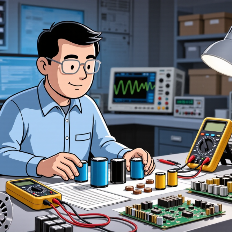
Table of Contents [Hide]
Identify Application Voltage, Frequency, and Capacitance Requirements
How to Choose Capacitors and Capacitance for Your Needs?
Start with the application voltage. Measure the highest normal voltage, including startup surges and switching spikes. Select a rated voltage above that value, not equal to it. Many engineers keep 20–30% voltage margin, although harsh circuits may require more. IEC 60384-1 emphasizes rated voltage, temperature, endurance, and reliability testing for fixed capacitors.
Temperature matters. A capacitor near a hot heat sink may lose capacitance faster than expected. My early design mistake was checking only the printed voltage rating. That shortcut was wrong.
Frequency determines impedance. Use Xc = 1/(2πfC) to estimate capacitive reactance.
At 60 Hz, a 10 µF capacitor has about 265 ohms of reactance. At 10 kHz, the same part falls below 2 ohms.
Switching supplies also create ripple currents, so capacitance alone cannot define performance. Check ripple-current ratings, ESR, and self-resonant frequency.
IEEE 519-2022 commonly uses a 5% total voltage-distortion limit for low-voltage systems at the point of common coupling. Harmonic currents can heat capacitors unexpectedly.
Estimate capacitance from load behavior, not habit. For smoothing, calculate allowable ripple voltage and load-current changes. For motor correction, include system frequency and harmonic conditions.
The International Energy Agency reported that global electricity demand increased 2.2% in 2023 and may grow about 3.3% annually through 2026. More electronic loads mean more switching noise and distortion.
A capacitor that works on a quiet bench may struggle in a crowded panel.
Recheck measurements after installation. Reality is less tidy.

© Copyright - Pro Tool & Supply - Site by SVM E-Marketing Solutions - Sitemap
- Privacy policy