- Products
- Air Compressors & Air Tools
- Climate Control
- Compaction Equipment
- Concrete Cutting Tools & Equipment
- Concrete and Masonry
- Demolition & Excavation
- Electrical & Mechanical
- Fasteners and Anchoring Adhesives
- Floor Protection
- Generators and Welders
- Hand Tools
- Heaters
- Janitorial and Office Supplies
- Jobsite Protection
- Ladders & Storage
- Lighting & Lighting Accessories
- Man Lifts
- Material Handling Equipment
- Power Tools
- Pressure Washers & Pumps
- Safety Gear
- Safety Products
- Saws
- Surface Preparation
- SEASONAL PRODUCTS
- Rentals
- Air Compressor and Air Tool Rentals
- Climate Control Rental
- Compaction Rentals
- Concrete Equipment Rentals
- Demolition & Excavation Equipment Rentals
- Concrete Floor Grinder Rentals
- General Construction Equipment Rentals
- Generator Rentals and Welder Rentals
- Heater Rentals
- Light Tower Rentals
- Man Lift Rentals in Massachusetts and Rhode Island
- Material Handling Equipment Rentals
- Pressure Washer & Pump Rentals
- Saw Rentals in New England
- SEASONAL PRODUCTS
- Products
- Air Compressors & Air Tools
- Climate Control
- Compaction Equipment
- Concrete Cutting Tools & Equipment
- Demolition & Excavation
- Electrical & Mechanical
- Floor Protection
- Generators and Welders
- Construction Heaters
- Construction Ladders, Staging, & Storage
- Construction Lighting
- Man Lifts
- Material Handling Equipment
- Industrial Janitorial and Office Supplies
- Pressure Washers & Pumps
- Construction Safety Products
- Construction Safety Gear
- Surface Preparation
- Building Protection
- Diesel Accessories
- Zero Emissions
- Rentals
- Air Compressor and Air Tool Rentals
- Climate Control Rental
- Compaction Rentals
- Concrete Equipment Rental
- Demolition & Excavation Equipment Rental
- General Construction Equipment Rental
- Generator Rentals and Welder Rentals
- Construction Heaters Rental
- Light Tower Rentals
- Man Lift Rentals
- Material Handling Equipment Rental
- Pressure Washer & Pump Rentals
- Saw Rentals in New England
- Concrete Floor Grinder Rentals
- Zero Emissions Rentals
- Repairs & Used
- Parts
- Blog
- Services
- Resources
- About Us
- Contact Us
Sales & Rental of Construction | Industrial Equipment & Supplies


What Is an Insulated Wire Terminal and How Does It Work?
An insulated wire terminal joins a conductor to another wire, component, or connection point. Insulated Wire Terminals add a protective sleeve around the crimped connection. This sleeve usually uses nylon, PVC, or heat-resistant materials. It helps reduce accidental contact, moisture exposure, and short-circuit risks during normal use.
The working principle is straightforward. A metal barrel grips the stripped conductor. A crimping tool compresses the barrel around the wire strands. The insulation sleeve then covers the exposed metal area. A properly matched terminal should hold firmly without cutting through the conductor. It should also fit the wire size, insulation diameter, and electrical load.
Small details matter. Too little pressure creates a loose connection. Excessive pressure may damage the strands. A reliable installation often includes a visual inspection and a gentle pull test. For critical equipment, installers should follow manufacturer instructions and relevant standards, such as applicable UL or IEC requirements. Requirements can vary by region and application.
The process sounds simple. It is easy to underestimate.
This guide explains what insulated wire terminals are, how they work, and where they are commonly used. It also examines terminal materials, crimp profiles, wire compatibility, and practical installation checks. Technical specifications remain more reliable than appearance alone. A bright, clean crimp may still be mechanically weak. That point deserves attention. Even experienced workers can miss a partially inserted conductor or the wrong terminal size. Careful preparation, suitable tools, and repeatable inspection make the connection safer and more dependable.
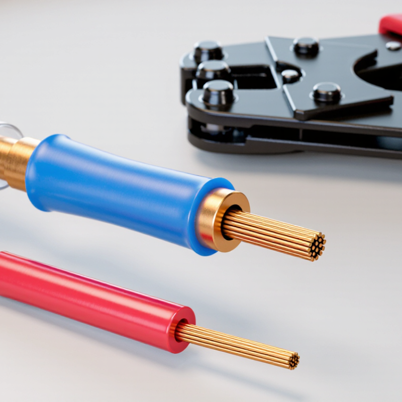
Table of Contents [Hide]
What Is an Insulated Wire Terminal? Definition and Electrical Function
An insulated wire terminal is a metal connector covered by a nonconductive sleeve. It joins a stripped wire to another electrical point, such as a stud, socket, or circuit component. The metal section carries current. The sleeve does not. It reduces accidental contact with nearby conductors and helps protect the connection from abrasion, moisture, and minor movement. Common forms include ring, fork, pin, and butt terminals. Their shapes serve different connection points, but their basic purpose remains the same: create a stable electrical path.
During installation, the wire enters a metal barrel and is compressed with a suitable crimping tool. Correct pressure deforms the barrel around the conductor, producing a low-resistance joint and strong pullout resistance. The terminal must match the wire size, conductor type, and fastening method. A loose crimp can heat under load. An oversized terminal may hold poorly. The insulation sleeve should remain intact near the crimp, while no copper strands should extend beyond the barrel. A gentle pull test often reveals a weak connection.
Insulation improves safety, but it does not repair poor workmanship. Dirt, incorrect stripping length, repeated bending, or an under-tightened screw can increase resistance. In vibrating equipment, failure may appear slowly. The circuit may work at first. Temperature rise is a warning sign. Experienced technicians also inspect the terminal after crimping, checking for cracks, uneven compression, and exposed conductor. Standards and manufacturer instructions should guide tool selection and testing. No terminal is foolproof. Even a neat-looking joint deserves a careful second look.
What Is an Insulated Wire Terminal and How Does It Work? - Definition and Electrical Function
| Data Dimension | Key Information | Electrical or Mechanical Role | Practical Consideration |
|---|---|---|---|
| Definition | An insulated wire terminal is a connector attached to the end of an electrical conductor and covered with a nonconductive sleeve or housing. | Creates a controlled connection between a wire and another conductor, terminal post, stud, screw, or electrical device. | The terminal must match the conductor size, connection method, and expected electrical load. |
| Main Components | Typical parts include a conductive barrel, a connection section such as a ring, fork, pin, or tab, and an insulating sleeve. | The metal portion carries current, while the insulation helps prevent unintended contact with nearby conductive parts. | The barrel should fully contain the stripped conductor before crimping. |
| How It Works | The wire is stripped to the specified length, inserted into the terminal barrel, and mechanically compressed with a suitable crimping tool. | A properly formed crimp provides metal-to-metal contact and a low-resistance current path. | A loose crimp can increase resistance, generate heat, and allow the conductor to pull out. |
| Current Path | Current flows from the wire strands into the conductive barrel and through the terminal’s contact section. | The terminal transfers electrical energy while maintaining a stable junction between conductors. | Contact surfaces should be clean, secure, and free from damage or excessive oxidation. |
| Insulation Function | The insulating sleeve covers part of the conductive terminal and the wire-entry area. | Reduces the risk of accidental short circuits, contact with adjacent conductors, and unintentional electrical bridging. | Insulation is not a substitute for correct spacing, enclosure protection, or de-energized maintenance procedures. |
| Common Terminal Shapes | Common forms include ring terminals, fork terminals, pin terminals, butt-splice terminals, and quick-disconnect terminals. | Each shape is designed for a different connection interface, such as a stud, screw, wire-to-wire joint, or mating tab. | Select the shape according to the hardware and whether the connection must remain attached when a screw is loosened. |
| Conductor Compatibility | Terminals are manufactured for specific wire cross-sectional areas or gauge ranges and may be intended for stranded, solid, or fine-stranded conductors. | Correct sizing allows the terminal to grip the conductor without cutting strands or leaving excessive movement. | Do not force an oversized wire into a small barrel or use a terminal outside its marked conductor range. |
| Voltage and Current Rating | Ratings depend on the terminal’s material, geometry, insulation system, conductor size, installation method, and environmental conditions. | The connection must safely carry the intended current and withstand the applied voltage without overheating or insulation breakdown. | Use the rating stated for the specific terminal rather than assuming all terminals of the same shape have identical ratings. |
| Crimping Process | A crimping tool deforms the barrel around the conductor to create a permanent mechanical and electrical connection. | The compressed joint holds the strands together and helps maintain consistent contact pressure. | Use the correct die cavity and complete the crimp in the intended location on the barrel. |
| Strain Relief | Many insulated terminals include a rear insulation-support section that grips the wire insulation. | Helps reduce flexing and transfer of pulling forces directly to the electrical crimp area. | The insulation-support crimp should hold the insulation without cutting through it. |
| Typical Materials | The conductive section is commonly made from copper or a copper alloy, while the sleeve may use an electrical insulating polymer. | The conductor material provides electrical conductivity; the sleeve provides electrical separation and physical protection. | Material selection should account for corrosion exposure, temperature, flexibility, and compatibility with the connected conductors. |
| Inspection Points | Inspect the crimp for correct placement, full conductor insertion, secure retention, intact insulation, and absence of exposed unintended strands. | Visual and mechanical checks help confirm that the connection is suitable before energizing the circuit. | A gentle pull test may reveal an incomplete or improperly positioned crimp, subject to the applicable work procedure. |
| Typical Applications | Used in control panels, vehicle wiring, appliances, industrial equipment, power distribution assemblies, and low-voltage electrical systems. | Provides organized, serviceable, and repeatable wire termination points. | The terminal and installation method must be appropriate for the system’s voltage, current, vibration, temperature, and environmental conditions. |

© Copyright - Pro Tool & Supply - Site by SVM E-Marketing Solutions - Sitemap
- Privacy policy